What’s New in ProgeCAD 2024
ProgeCAD 2024 is based on the latest IntelliCAD 11.1 source code. Hundreds of bugs fixed, new features and improved interface.
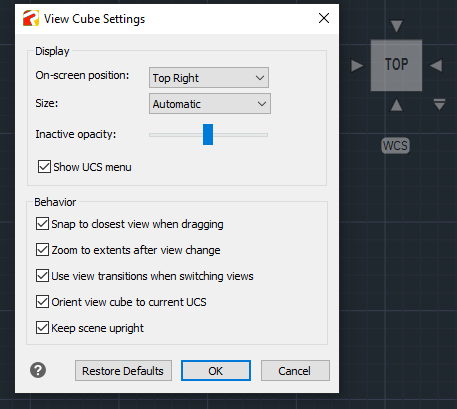
New command/function VIEWCUBE
The View Cube is a convenient way to control and manipulate the model space viewing
angle in progeCAD. The cube can be clicked and held to rotate the model space around, or the side, edge or corner of the cube can be selected to move it to another view. There is also a coordinate system drop-down list underneath the View Cube. Using this list, you can select custom saved coordinate systems, or reset and select the WCS. There is also a dialog to manage all the View Cube Settings.
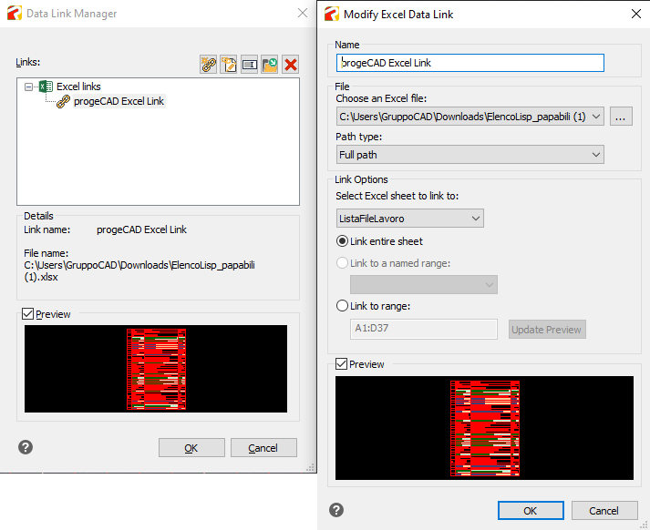
New command/function DATALINK
Data linking is the ability to link a Microsoft Excel spreadsheet to a progeCAD table dynamically linked to the external file. The best thing about data linking is that any changes that you make to the Excel spreadsheet will update the progeCAD table. Plus, if you set it up this way, you can edit the table and it can write back to the spreadsheet.
NOTE: The DATALINK function can be used as a single command, or from the table creation dialog.
XLSIMPORT command
Imports directly an .xls or .xlsx file into a new static progeCAD Table. The imported data fill a new table that is created automatically during import, and the new table is formatted automatically to match the format of the original spreadsheet.
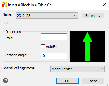
Insert blocks preview into Table Cells
When you insert a block into a table cell, either the block can automatically fit to the size of the cell, or the cell can adjust to accommodate the size of the block. Blocks can be inserted from the shortcut menu. Multiple blocks can be inserted in a cell. If there is more than one block in a cell, use the Manage Cell Content dialog box to customize the way the cell content is displayed.
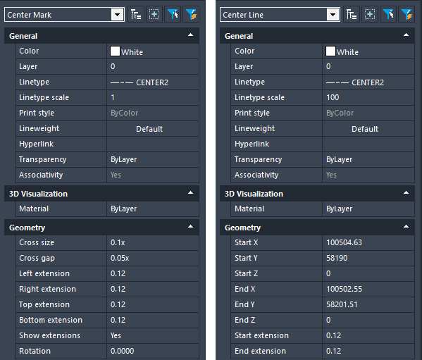
New CENTERMARK and CENTERLINE entities
Center Marks and Centerlines are dimensioning references to centers and axes of symmetry. Center Marks and Centerlines are associative objects. If you move or modify the associated objects, the center marks and centerlines adjust accordingly.
From the Properties palette, you can control their geometry and visibility. Current Layer Override: you can specify a default layer that is different than the current layer by specifying the layer with the CENTERLAYER system variable.
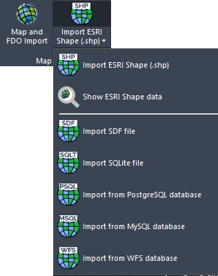
New command MAPIMPORT
Geo Data and FDO Import Inserts geometries from SDF files (SDF is a native Autodesk® geospatial file-based format optimized for storing large classified data sets), SQLite and SHAPE (esri) files, or can use a database server service like WFS (the Web Feature Service allows users to share geospatial /or non-spatial data over the Internet. Thus, feature services can be consumed through the Internet in WebMaps, desktop and web applications.), PostgreSQL or MySQL.
Improved OFFSET command
Added “Layer” and “Erase” options in the OFFSET command
“Erase” erases the source object after it is offset.
“Layer” determines whether offset objects are created on the current layer or on the layer of the source object.
New command MAPIINSERT
Multiple images insertion Allows to insert multiple images at the same time (useful for georeferenced images).
New command BREAKATPOINT
Splits 2D entities such as lines, arcs, polylines, infinite lines, rays, splines into two entities at a single break point. Closed entities cannot be split at a single break point.
Working with BIM files:
Support for Autodesk® Revit® 2023 files.
Import IFC and REVIT (up to version 2022) with Layers progeCAD imports BIM files with the layers structure reading from the IFC or Revit files. Through the new variable BIMIMPORTLAYER, the user can choose the level of the tree layers. BIMIMPORTLAYER values 0 = no layers 1 = objects layers 2 = categories/levels layers (default)
New variable BIMIMPORTACTION controls actions after the import of BIM files (RVT, IFC). The sum of the values configures the behavior of progeCAD : 1 = make a zoom extent after import 2 = set isometric view after import 4 = Activate the Realistic Visual Style after import (eg. Set to 7 to activate all behaviors, 4 is the default)
In the BIM Properties pane, create and assign Visibility States.
Select, attach, and manage .IFC and .RVT/.RFA underlays using the progeCAD Explorer.
Use the Audit command to check for errors in .IFC files that are attached as underlays.
New SURFEXTRACTCURVE command
Creates curves in the U and V directions on a Surface or on a 3D solid. The curves can be lines, polylines, arcs, or splines depending on the shape of a 3D object.
New command 3DWALK
Changes the 3D view in a drawing interactively to create the appearance of walking through the model. Manage Settings with the 3DWALKFLYSETTINGS command.
New command 3DFLY
Changes the 3D view in a drawing interactively to create the appearance of flying through the model. Manage Settings with the 3DWALKFLYSETTINGS command.
New command 3DPOSITIONER
Displays a visual aid, or gizmo, used to move and rotate entities in the three-dimensional space.
New function for the UCS command
Now it is possible to select Solid entities or Surfaces to define a new UCS.
New command AIDIMSTYLE
Allows you to create a Dimension Style from an existing dimension. Say you have a dimension and you change its properties by overriding such elements: extension line color, text color, arrowhead size, and text font. Just run the command AIDIMSTYLE and select the dimension and a new style will be created with these properties.
New command LAYMRG
Merge Layers You can reduce the number of layers in a drawing by merging them. Objects on merged layers are moved to the target layer, and the original layers are purged from the drawing.
New Preview Sheet (paper and margins) in the print dialog box.
Improved Explode command
Blocks Filter The “Blocks” option is now available to automatically filter selected objects in order to preserve objects other than blocks, such as Array, Polylines, MTexts, etc.
New command WHOHAS
Information on the drawing user and usage Displays information about an open drawing file. You can use WHOHAS to find out who has a specified drawing file open. After you specify a drawing file, information is displayed that includes the full path of the file, the current user’s login name, computer name, and the date and time that the drawing file was opened.
Improved APPLOAD command
Creates Startup Suites which allow you to specify the custom applications to load automatically when progeCAD starts.
New functions for the PDFEXPORT command
The New interface for exporting drawings to PDF. Now it is possible to export all layouts and also the model space, based on the user selection, to create multi-page PDF files.
Improved QDIM command
Updated the Quick Dimension command and added the new Settings option in order to manage the associative dimension priority to the Endpoint or to the Intersection.
New command REGENVISIBLE regenerates entities only in the visible area.
Improved TOOLPALETTE
Drag an entity from a drawing and drop it on a tool palette to add the corresponding entity-creation command to the tool palette.
Improved Geolocation function
New dialog box for adding a geographic location to a drawing.
New GEOMAPSERVICE command
Use the Map Service command to turn geographic map services on and off. When off, the program is prevented from accessing the Internet to display the online map, and the Mark Position, Capture Area, and Reload Image commands are unavailable.
Command Line Font. Displays the Command Bar Font dialog box.
Improved Big Font substitution
Now it is possible to select a replacement font by searching directly on the PC, using the Browse function and not only among the predefined choices.
New command
TABLE In the command bar, type -TABLE to insert a table without the dialog box.
Network license Groups (Apply to NLM licenses only)
The feature to assign a membership group to each NLM license which allows to break the total number of available NLM licenses into some independent groups. In this way, licenses can be divided among specific offices / work groups.
STEP/IGES Import
New Object creation option. You can configure your preferred 3D CAD entity type when importing 3D external files. “Automatic” is the default and recommended mode. The new option is available in the IGESSTEPOPTIONS dialog.
New function Restore suppressed messages
In the Options dialog, it is now possible to restore the help and warning messages that were definitively hidden by the user.
New Express command Smart Join
Joins lines, polylines, splines into a single polyline
New CTRL+R function
Switches between tiled viewports in the Model tab or floating viewports in the current layout
• PERFORMANCE. Faster polyline vectorization.
• PERFORMANCE. The Quick Select command is faster by 2x in large drawings.
ProgeCAD 2024 Price
| ProgeCAD 2024 SL India Version | 12,000/- Rs |
| ProgeCAD 2024 NLM India Version | 13,000/- Rs |
| ProgeCAD 2024 India Version SL/NLM Upgrade from Version 2022 | 4,900/- Rs |
| ProgeCAD 2024 India Version SL/NLM Upgrade from Version 2021 or Older | 6,000/- Rs |
| ProgeCAD 2024 SL India Version – Competitive Upgrade from other CAD Software | 9,000/- Rs |
| ProgeCAD 2024 NLML India Version – Competitive Upgrade from other CAD Software | 9,000/- Rs |
| ProgeCAD 2024 SL India Version Corporate One Site | 6,05,000/- Rs |
| ProgeCAD 2024 SL India Version Corporate One Country | 24,20,000/- Rs |